
Intervalometer
Unleash the power of timelapse and astrophotography
Introduction
Recently, I started being interested in timelapse photography. It can give life to a scene, add dynamics to star photographs, etc, etc. Timelapse photography is not new, I am “late” getting into it, but why not?
Making a timelapse involves taking a sequence of pictures at a regular interval, said pictures are then combined later into a video. Although some cameras have the timelapse capability built-in, I find the level of control is not adequate. Also, I still use an old DSLR that does not have such a feature. External devices, aptly named “intervalometers”, are available on the market.
There are a couple of categories, ranging in price from affordable (~$50) to outright overpriced ($350+). The cheap models are fine feature wise but they don’t allow for the pictures to be reviewed (more on that later). The more expense devices are more flexible. However, why not have fun designing one?
What are the uses of an intervalometer ?
The most common use is, of course, for timelapse photography, a sequence of images is later combined to make a video.
Another use is for astrophotography: a series of pictures are taken to later be stacked to reduce the noise. A piece of software such as “Star Stacker” combines the photographs into a single image. Typically, 9 to 16 images are taken.
Yet another use is to simply take the same composition multiple time to stack them in order to, again, reduce the noise. This is useful for photographs of s static composition taken at night or at high ISO.
There are surely other uses I am not aware of…
How does an intervalometer work anyway ?
The camera is triggered, via a cable (or remotely for fancy devices), at an interval. The exposure time is either determined by the camera or programmed in the intervalometer. For flexibility, I want to set both the interval and exposure times.
To understand the limitations of most intervalometers on the market, we need to first to remember the shutter lease button of a camera has two positions: mid-way for focusing, pressed down for exposing. Cable releases work in the same way. Canon cameras implement this with a 3-pin connector, allowing to control focus and trigger (Other camera manufacturers have their own version).
Most intervalometers available on the market control the focus signal all the time, which prevents the photographer from reviewing an image (for exposure, in case light changes) or accessing other camera controls. Being unable to review an image as the timelapse is running is an issue, as the only way to review exposure is OK is by stopping the sequence.
So, the design of our device must take this into account…
What features ?
That’s where we list our wishes and desires, what we want to do with the intervalometer.
To control exposure time and the interval/period (duh!)
To control multiple cameras at once
To allow for picture review as the timelapse is going
This design will focus on Canon cameras (the design can be adapted to other brands. Very likely)
To provide a simple yet effective user interface
A small form-factor obviously, easily carried around in a backpack
To power the device with rechargeable batteries
Now…
It’s design time
How will we make this device? We want a design that is as cheap as possible (as in “no need to spend a ton of money”) and a lot of fun as well.
We need a computer, small and lean in energy consumption capable of running MicroPython.
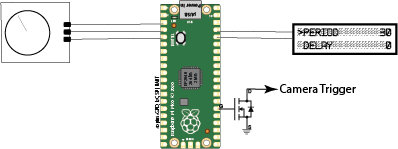
We need a display. It so happens I have a pile of 2-line LCD displays in my garage (like these).
We also need a way to set parameters like exposure time, the number of exposures, the interval time, etc. The user interface must enable us to select a parameter and to change its value (increase or decrease). Buttons can be used of course (5 of them are needed). A rotary encoder with a built-in switch can also be used. This presents two avantages: it reduces the number of components needed and since I have never used one, it’s growth.
So, we’ll use a Raspberry Pi pico for the computer. It provides all the connectivity we need (pins, i2c for the display). Software wise, micro python is available. It provides libraries to control the LCD, to manager the rotary encoder.
On to designing the software…
Designing software can be achieved in many different ways. The code can be very integrated (i.e. difficult to reuse in other projects) or can be written around concepts. Code can be elegant, easily readable or can look like a plate of spaghetti.
Since I have other projects in mind that will use rotary encoders, displays, etc, it’s important to define concepts and design code to isolate features with clean interfaces between functional blocks.
The rotary encoder is the input device that is used to select a “parameter”, to set a parameter value and to start/stop the timelapse. The user interface is displayed on a 2-line/16 character LCD.
We have to recognize that the time critical feature is the control of the camera, obviously. No element of the UI is time critical.
The UI is “event driven”:
- events are queued in an event queue.
- events are generated when the rotary encoder is pressed or turned
- events are generated when the timer is running
- the events are consumed by an event processing loop, that updates the UI accordingly.
What is the most important feature here ?
The accuracy of exposure times… The intervalometer will control the camera (assumed to be set to ‘bulb’ mode for flexibility) so it is important that no delay impacts the control of the camera. The timer will control the camera directly and will notify of the completion of exposure and review periods by queuing messages to be processed by the loop so the user interface can be updated appropriately.
A user interface on a spacious display of 2 lines of 16 characters
The user interface will not be graphic-rich… And that’s ok. There’s a plenty to be done with 2 lines of text.
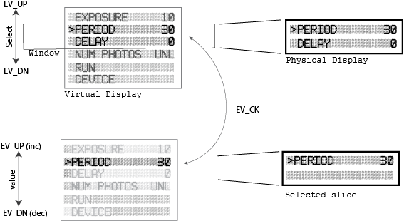
The user interface must appear on the 2-line LCD. For clarity and readability, it seems adequate to show one parameter per line. Since we have more than two parameters (exposure time, period, delay and number of photos), the user interface relies on a virtual display, that can have as many lines of text (16 characters) as needed. As the user turns the knob of rotary encoder (RE), a “window” slides up or down the virtual display according to the direction of the RE’s knob and the 2 selected lines of the virtual display are rendered to the physical display (i.e. the LCD). For every turn of the RE’s knob, either EV_UP or EV_DN is queued.
Each line in the virtual display is a “display slice”, that is assigned a virtual line, a width, a label (the text) and a range of values. The slice renders its state to the virtual display whenever necessary.
As the RE’s knob is turned, a parameter is selected, a “>” being shown on the corresponding line. As shown above, the period parameter is selected. If the user presses the RE’s button, EV_CK is queued, the event processing loop dispatches events to the display slice of the selected line: EV_UP and EV_DN respectively increase or decrease the parameter’s value, EV_CK tells the processing loop to resume event processing.
A display slice can be implemented as a command, e.g. start the intervalometer. Whenever the event CK is processed for such a display slice, a new user interface is created; it initializes the timer and handles the events emitted by it (TK for the count down and CC when the countdown has completed).
There is another slice that turns off the device when CK is received. UP/DN returns to the main user interface.